usb2neogeo
USB/BT controllers to Neo Geo / SuperGun.
Overview
Connects USB and Bluetooth controllers to Neo Geo consoles (AES/MVS) and SuperGun arcade boards via GPIO-based active-low output to a DB15 connector. Supports 7 button mapping profiles optimized for different arcade stick layouts and pad configurations. Uses open-drain logic to safely interface 3.3V GPIO with 5V Neo Geo hardware.
Input
Output
Neo Geo Output -- Active-low GPIO via DB15 connector.
Core Configuration
| Setting | Value |
|---|---|
| Routing mode | SIMPLE (1:1) |
| Player slots | 1 (shift on disconnect) |
| Max USB devices | 1 |
| Profile system | 7 profiles, saved to flash |
Profiles
Hold Select for 2 seconds, then press D-Pad Up/Down to cycle.
| Profile | Description |
|---|---|
| Default | Standard 1L6B layout |
| Type A | 1L6B aligned to right side of 1L8B stick |
| Type B | Neo Geo MVS 1L4B layout |
| Type C | Neo Geo MVS Big Red layout |
| Type D | Neo Geo MVS U4 layout |
| Pad A | AES pad, classic diamond (A/B/C/D on face buttons) |
| Pad B | AES pad, KOF/fighting style |
Default Profile
Standard arcade mapping for 1L6B in 1L8B fightsticks:
| USB Input | Neo Geo Output |
|---|---|
| B1 (Cross/A) | B4 / K1 / D |
| B2 (Circle/B) | B5 / K2 / Select |
| B3 (Square/X) | B1 / P1 / A |
| B4 (Triangle/Y) | B2 / P2 / B |
| L1 (LB/L) | (disabled) |
| R1 (RB/R) | B3 / P3 / C |
| L2 (LT/ZL) | (disabled) |
| R2 (RT/ZR) | B6 / K3 |
| S1 (Select) | Coin |
| S2 (Start) | Start |
| D-Pad | D-Pad |
| Left Stick | D-Pad |
Type A Profile
1L6B aligned to right side of 1L8B fightsticks:
| USB Input | Neo Geo Output |
|---|---|
| B1 (Cross/A) | (disabled) |
| B2 (Circle/B) | B4 / K1 / D |
| B3 (Square/X) | (disabled) |
| B4 (Triangle/Y) | B1 / P1 / A |
| L1 (LB/L) | B3 / P3 / C |
| R1 (RB/R) | B2 / P2 / B |
| L2 (LT/ZL) | B6 / K3 |
| R2 (RT/ZR) | B5 / K2 / Select |
Type B Profile
Neo Geo MVS 1L4B layout:
| USB Input | Neo Geo Output |
|---|---|
| B1 (Cross/A) | B1 / P1 / A |
| B2 (Circle/B) | B5 / K2 / Select |
| B3 (Square/X) | B2 / P2 / B |
| B4 (Triangle/Y) | B3 / P3 / C |
| L1 (LB/L) | (disabled) |
| R1 (RB/R) | B4 / K1 / D |
| L2 (LT/ZL) | (disabled) |
| R2 (RT/ZR) | B6 / K3 |
Type C Profile
Neo Geo MVS Big Red layout:
| USB Input | Neo Geo Output |
|---|---|
| B1 (Cross/A) | B1 / P1 / A |
| B2 (Circle/B) | B5 / K2 / Select |
| B3 (Square/X) | (disabled) |
| B4 (Triangle/Y) | B2 / P2 / B |
| L1 (LB/L) | B4 / K1 / D |
| R1 (RB/R) | B3 / P3 / C |
| L2 (LT/ZL) | (disabled) |
| R2 (RT/ZR) | B6 / K3 |
Type D Profile
Neo Geo MVS U4 layout:
| USB Input | Neo Geo Output |
|---|---|
| B1 (Cross/A) | B5 / K2 / Select |
| B2 (Circle/B) | B6 / K3 |
| B3 (Square/X) | B1 / P1 / A |
| B4 (Triangle/Y) | B2 / P2 / B |
| L1 (LB/L) | B4 / K1 / D |
| R1 (RB/R) | B3 / P3 / C |
| L2 (LT/ZL) | (disabled) |
| R2 (RT/ZR) | (disabled) |
Pad A Profile
AES pad, classic diamond (A/B/C/D on face buttons):
| USB Input | Neo Geo Output |
|---|---|
| B1 (Cross/A) | B1 / P1 / A |
| B2 (Circle/B) | B2 / P2 / B |
| B3 (Square/X) | B3 / P3 / C |
| B4 (Triangle/Y) | B4 / K1 / D |
| L1 (LB/L) | B6 / K3 |
| R1 (RB/R) | B5 / K2 / Select |
| L2 (LT/ZL) | (disabled) |
| R2 (RT/ZR) | (disabled) |
Pad B Profile
AES pad, KOF/fighting style:
| USB Input | Neo Geo Output |
|---|---|
| B1 (Cross/A) | B2 / P2 / B |
| B2 (Circle/B) | B4 / K1 / D |
| B3 (Square/X) | B1 / P1 / A |
| B4 (Triangle/Y) | B3 / P3 / C |
| L1 (LB/L) | B6 / K3 |
| R1 (RB/R) | B5 / K2 / Select |
| L2 (LT/ZL) | (disabled) |
| R2 (RT/ZR) | (disabled) |
Profile Diagrams


Supported Boards
| Board | Build Command |
|---|---|
| KB2040 | make usb2neogeo_kb2040 |
| Pico | make usb2neogeo_pico |
| RP2040-Zero | make usb2neogeo_rp2040zero |
Build and Flash
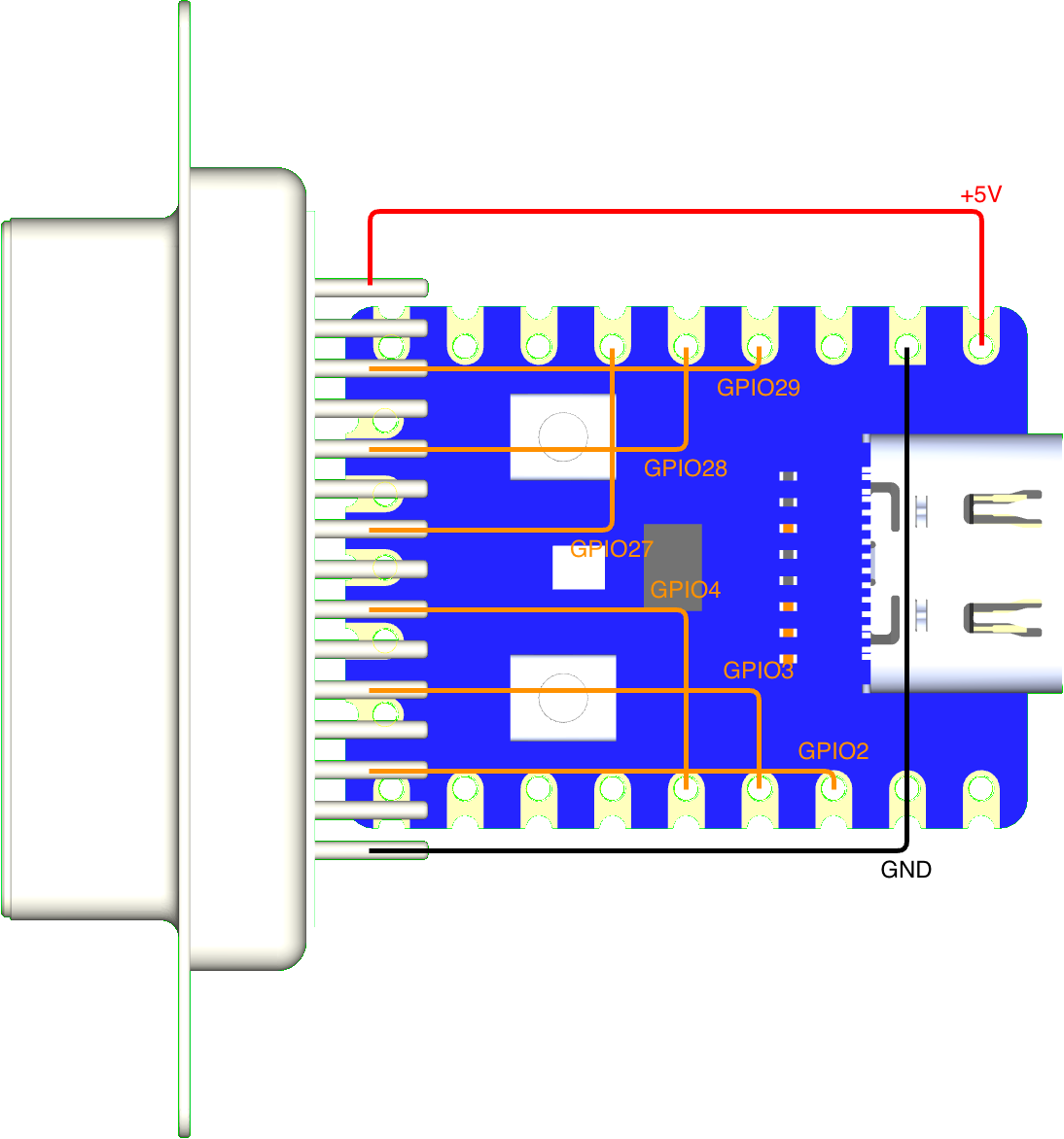
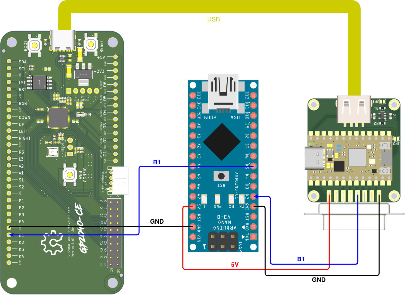
Wiring
KB2040 / Pico / RP2040-Zero
| KB2040 | Pico | RP2040-Zero | DB15 Pin | Neo Geo Function |
|---|---|---|---|---|
| GND | GND | GND | Pin 1 | Ground |
| GPIO 7 | GPIO 7 | GPIO 2 | Pin 2 | Button 6 / K3 |
| GPIO 6 | GPIO 6 | GPIO 3 | Pin 3 | S1 (Coin) |
| GPIO 5 | GPIO 5 | GPIO 4 | Pin 4 | Button 4 / D |
| GPIO 4 | GPIO 4 | GPIO 27 | Pin 5 | Button 2 / B |
| GPIO 3 | GPIO 3 | GPIO 28 | Pin 6 | Right |
| GPIO 2 | GPIO 2 | GPIO 29 | Pin 7 | Down |
| 5V | 5V | 5V | Pin 8 | +5V Power |
| N/C | N/C | N/C | Pin 9 | - |
| GPIO 20 | GPIO 20 | GPIO 9 | Pin 10 | Button 5 / Select |
| GPIO 18 | GPIO 18 | GPIO 10 | Pin 11 | S2 (Start) |
| GPIO 26 | GPIO 26 | GPIO 11 | Pin 12 | Button 3 / C |
| GPIO 27 | GPIO 27 | GPIO 12 | Pin 13 | Button 1 / A |
| GPIO 28 | GPIO 28 | GPIO 13 | Pin 14 | Left |
| GPIO 29 | GPIO 19 | GPIO 14 | Pin 15 | Up |
Voltage Protection
This implementation uses open-drain logic to prevent voltage collisions between 5V and 3.3V, ensuring the safety of your Neo Geo or arcade PCBs.
- Basic protection: Add a 1N4148 diode with the cathode (stripe) facing the RP2040.
- Maximum safety: Use level shifters such as the TXS0108E (bidirectional) or the 74LVC245A (unidirectional).
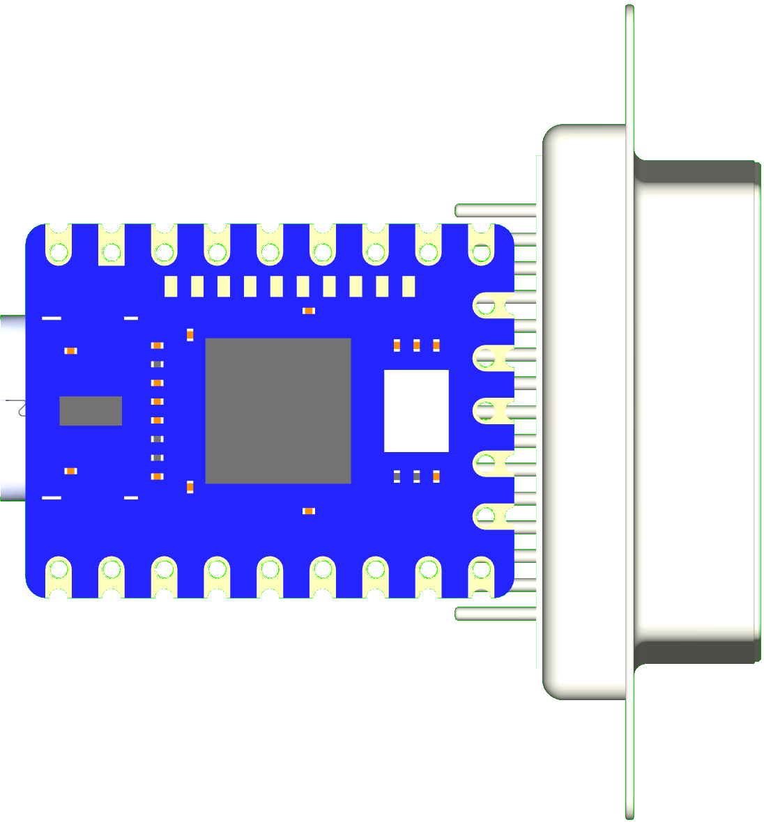
RP2040-Zero Direct Solder
Latency Testing
Troubleshooting
Controller not detected: - Check Neo Geo cable connections. - Ensure the DB15 cable is providing 5V on Pin 8 and GND on Pin 1. - Check data pin assignments in firmware.
Profile not saving: - Wait 5 seconds after changing the profile for the flash write to complete. - Reflash firmware if flash memory appears corrupted.