USB to GameCube Adapter
Build a USB/Bluetooth-to-GameCube adapter on an RP2040 board. The wiring is identical across the supported boards — only the build target and a couple of pad labels change.
Supported Boards
| Board | Build Target | 5V Pin Label | Notes |
|---|---|---|---|
| Adafruit KB2040 | usb2gc_kb2040 |
RAW | Bridge USB power pads (see Controller Input) |
| Raspberry Pi Pico | usb2gc_kb2040 |
VBUS | No onboard NeoPixel — controller status only via flash |
| Waveshare RP2040-Zero | usb2gc_rp2040zero |
5V | NeoPixel on GPIO 16; I2C remapped to GPIO 14/15 |
The Pi Pico runs the same firmware as the KB2040 — same RP2040 chip, same default GPIO map.
Parts Needed
- One of the boards above
- GameCube controller extension cable (cut to expose the five wires inside)
- USB-A female to USB-C male adapter (KB2040) or USB-A to micro-USB OTG adapter (Pi Pico) so USB controllers can plug into the board's host port
- Soldering iron and solder
Wiring
GameCube Connector
The GameCube controller port uses a proprietary connector. Cut a GC extension cable and wire the console-end plug to your board.
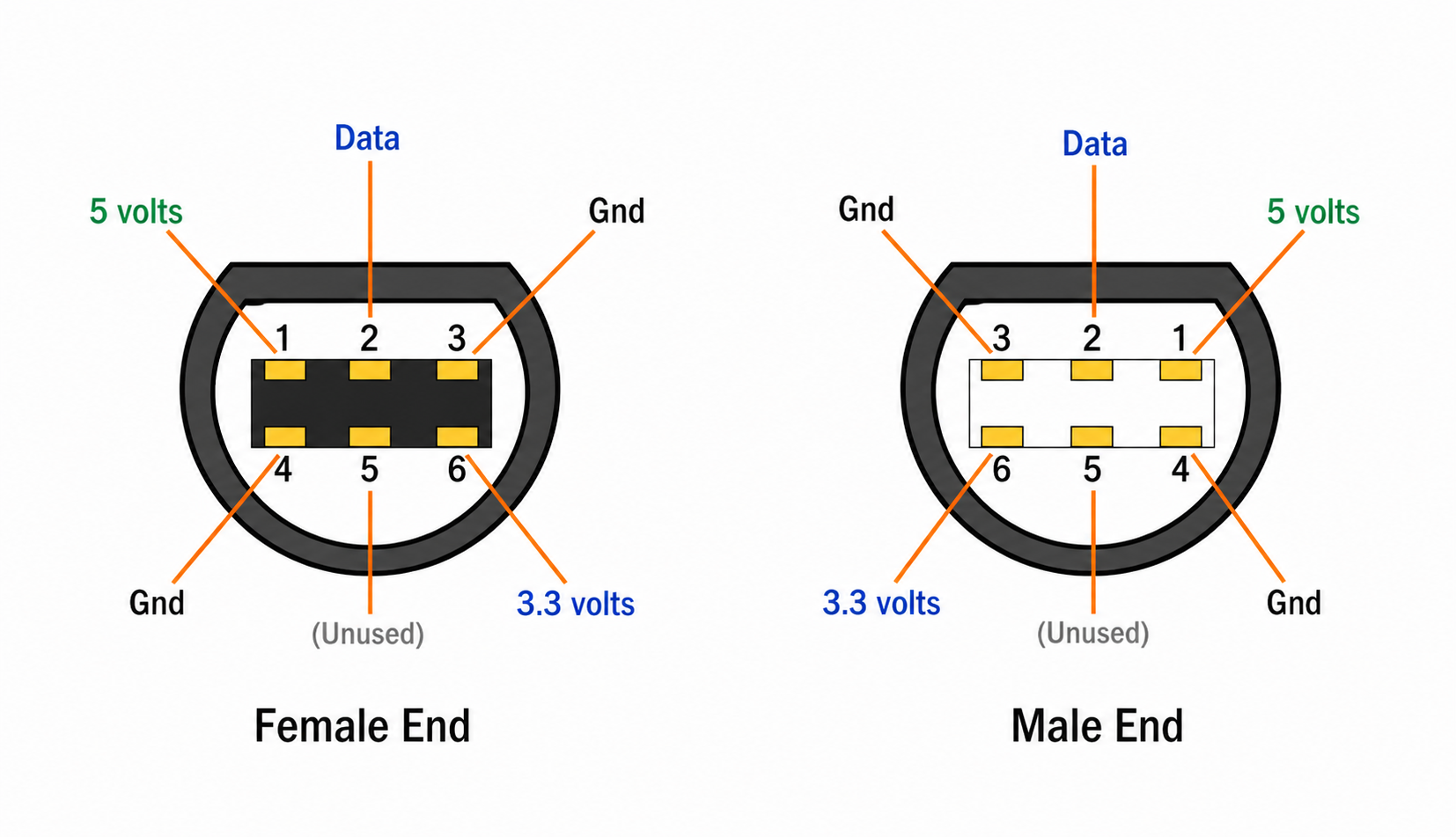
| GC Pin | Signal | RP2040 GPIO | Notes |
|---|---|---|---|
| 1 | 5V | RAW (KB2040) / VBUS (Pico) / 5V (RP2040-Zero) | Powers the board from the console |
| 2 | Data | GPIO 7 | Bidirectional joybus data line — and the console-detect line |
| 3, 4 | GND | GND | Tie both GC ground wires to the board's GND |
| 5 | (unused) | — | Leave disconnected |
| 6 | 3.3V | (leave disconnected) | Not used by current firmware — see below |
Only three signals matter: Pin 2 (data), Pin 1 (5V), and the two grounds. Get those right and the adapter works.
Cable wire colors vary by manufacturer — verify with a multimeter against the GameCube Pinout reference before soldering.
How console detection actually works
The firmware detects the console on the data line, GPIO 7 — not on a separate sense wire. At boot it configures GPIO 7 as an input with the RP2040's internal pull-down (~50 kΩ) and waits 200 ms. A powered console holds joybus high through its own ~1 kΩ pull-up, which easily wins against the pull-down:
- GPIO 7 reads HIGH → console present → play mode (controller input → GameCube)
- GPIO 7 reads LOW → no console → config mode (USB device with CDC for config.joypad.ai)
Detection then hands the pin over to the joybus PIO program, which reconfigures it with a pull-up.
Detection recovers on its own
At boot the probe settles for 200 ms, then samples for up to 800 ms — it switches to play mode the moment the data line goes high, so a console that is still powering up or a sample that lands inside a joybus burst no longer traps the adapter in config mode. And if it does come up in config mode (console powered on later), it keeps re-checking every 250 ms and reboots itself into play mode once the console has driven the line high steadily for ~2.5 s — unless a PC is actively connected over USB (config.joypad.ai), in which case it stays put so it can't reboot out from under your session. So plugging into a console works even if the adapter powered up first; you should no longer need to unplug and replug.
About GC Pin 6 (3.3V)
Earlier firmware sensed the console on a dedicated 3.3V wire at GPIO 6, and earlier versions of this guide told you to wire it. Detection moved to the data line in April 2026 (a12cc10b), and nothing in the firmware reads GPIO 6 any more — GC_3V3_PIN is still defined in gamecube_device.h but has no remaining callers. Leaving that wire connected on an existing build is harmless; on a new build, skip it. The reference photos below predate this change and still show the wire.
Don't power the adapter from both ends at once
The GameCube cable's 5V wire connects to the board's 5V/RAW/VBUS rail, which is the same rail as USB-C/microUSB VBUS through the board's protection diode. Plugging the adapter into a console and a computer's USB port at the same time ties two 5V supplies together — you can backfeed one into the other and stress the regulators on either side. Use the console's power for play mode, or USB power for config mode, never both.
Controller Input
The board's native USB port is the host. Plug your USB controller into it through a USB-A female adapter (USB-C for KB2040, micro-USB OTG for Pi Pico, USB-C for RP2040-Zero) — no GPIO wiring is needed for the host side. The joybus PIO program would clash with PIO-USB on RP2040, so this build deliberately uses the native USB controller for input and reserves PIO entirely for the GameCube data line.
KB2040: bridge the USB power jumper
On the KB2040, bridge the solder pads on the underside next to the USB-C port to enable full USB host power. Without the bridge, attached controllers may not get enough current to enumerate or run rumble. Pi Pico and RP2040-Zero have this routed by default and need no jumper.
For Bluetooth controllers, none of these boards have an onboard radio — plug a compatible USB BT dongle into the host port (use a USB hub if you also need a wired controller alongside). If you only want Bluetooth controllers, the Pico W build below is simpler.
Bluetooth-only: bt2gc on a Pico W
The Pico W and Pico 2 W have a built-in radio, so bt2gc takes Bluetooth controllers straight to the GameCube with no USB host and no dongle:
| Board | Build Target |
|---|---|
| Raspberry Pi Pico W | bt2gc_pico_w |
| Raspberry Pi Pico 2 W | bt2gc_pico2_w |
The GameCube wiring is identical — 5V to VBUS, data to GPIO 7, both grounds to GND, Pin 6 left disconnected. Console detection is the same self-recovering data-line probe described above.
Differences from the USB build:
- No USB-A adapter or OTG cable. The board's USB port is not a host in this build; it is only used for power, flashing, and config mode.
- No NeoPixel status LED —
bt2gcis built withCONFIG_NO_NEOPIXEL, so ignore the LED step under Testing. - Pairing is on the BOOTSEL button: click opens a 60-second pairing window, hold disconnects everything and clears all bonds. Leave the button reachable when you case the build.
- With no console attached, the adapter comes up as a USB device instead, so you can still reach config.joypad.ai; a double-click cycles the USB output mode there.
One controller drives the single GameCube port. Wiimotes, DualShock/DualSense, Switch Pro and the other Bluetooth pads in the BT controller list all route through the same drivers as bt2usb.
Reference Builds
KB2040
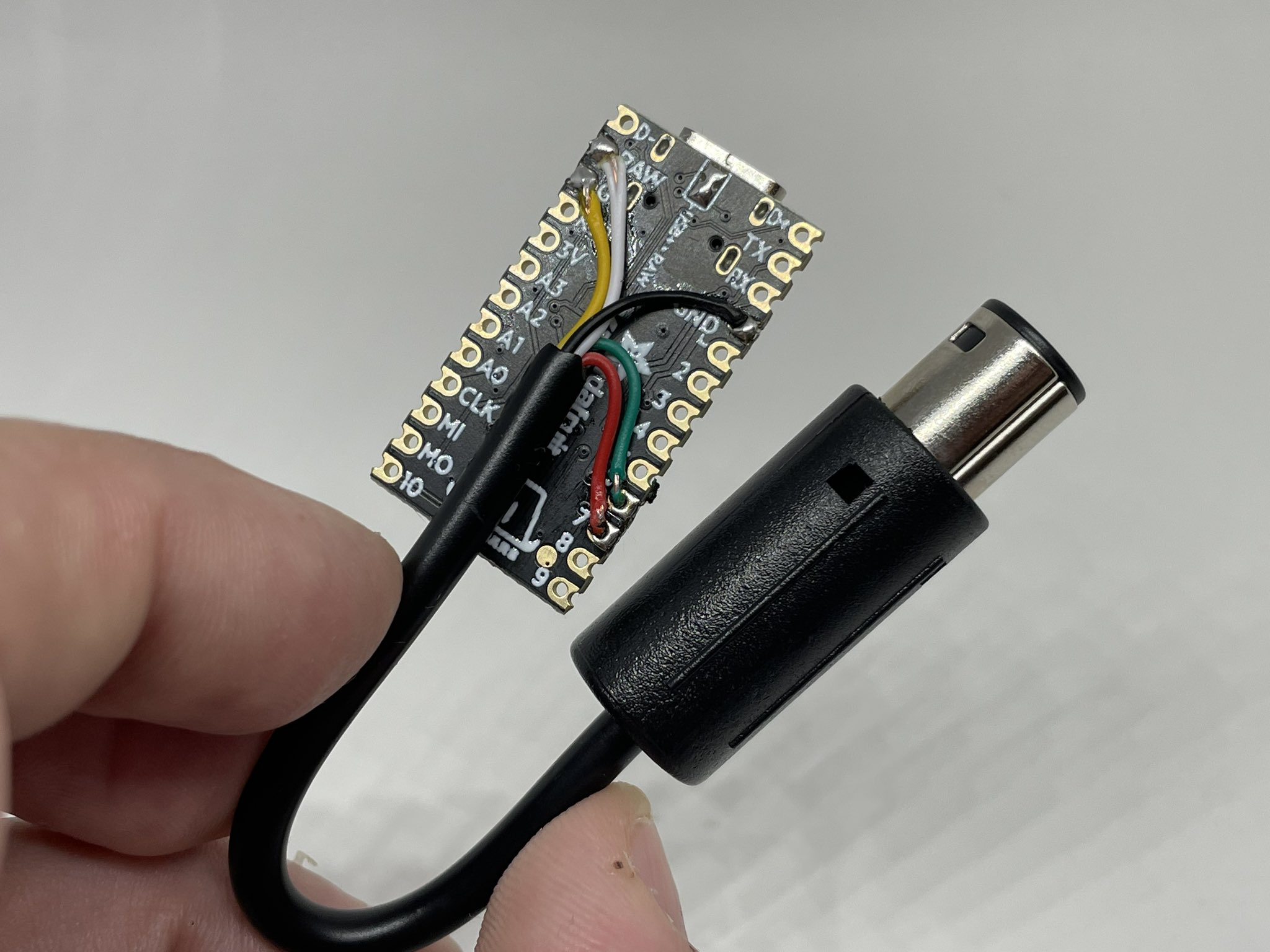
A finished KB2040 + GC cable build. Five wires from the cable land on RAW (5V), GPIO 6, GPIO 7 (data), and a pair of GND pads — this build predates the detection change, so the GPIO 6 wire is present but unused. A new build only needs four:
RP2040-Zero
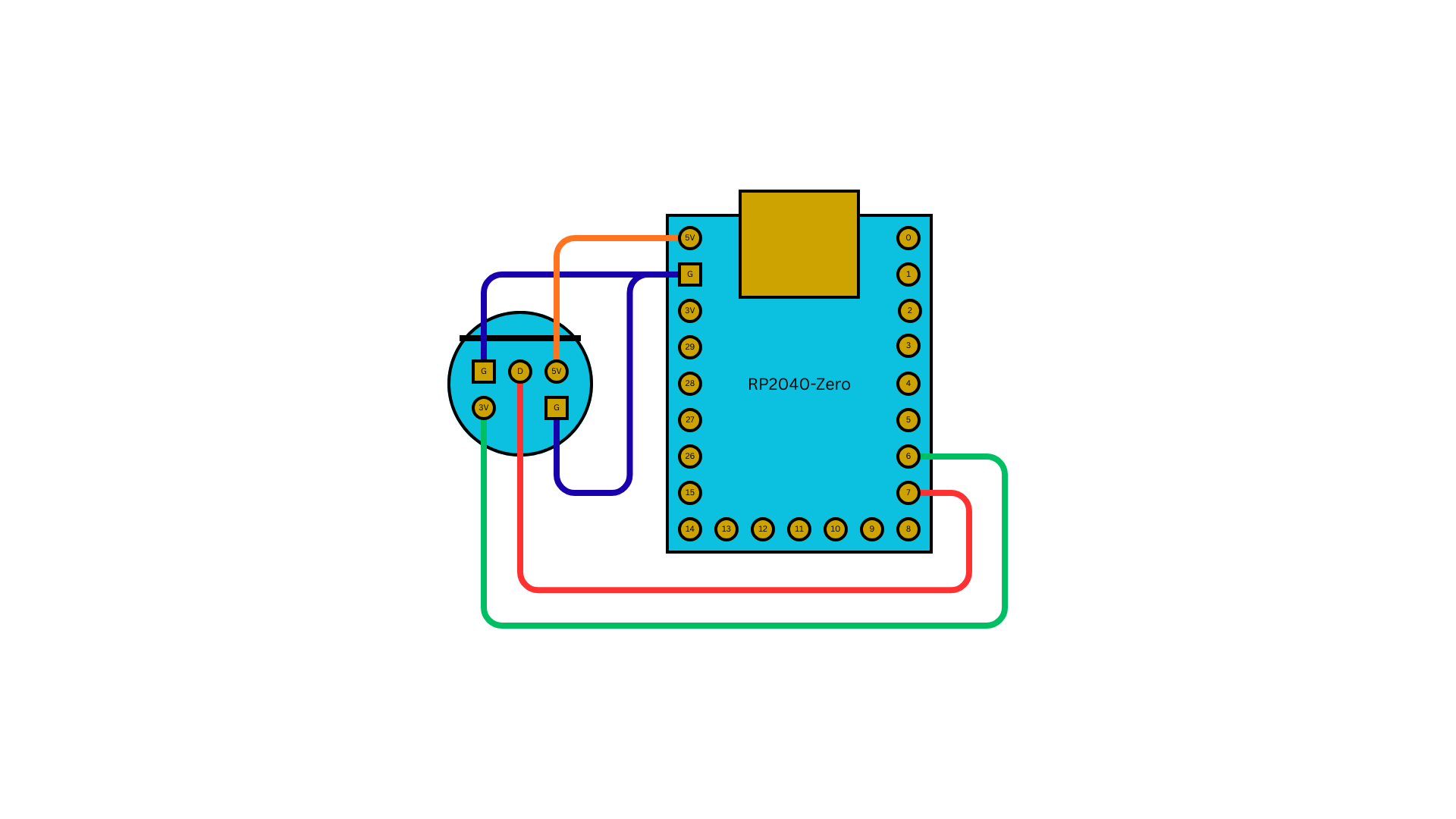
Same wiring on a Waveshare RP2040-Zero — only the physical pad locations and the NeoPixel/I2C settings change, the GC pins are identical (and the GPIO 6 wire shown here is likewise no longer needed):
Build and Flash
# KB2040 (also use this target on Pi Pico)
make usb2gc_kb2040
make flash-usb2gc_kb2040

# RP2040-Zero
make usb2gc_rp2040zero
make flash-usb2gc_rp2040zero
Flash by holding the BOOT button while connecting USB (or double-tap reset on boards that support it) to mount the RPI-RP2 drive, then drag-and-drop the .uf2. Output files:
releases/joypad_<commit>_usb2gc_kb2040.uf2releases/joypad_<commit>_usb2gc_rp2040zero.uf2
Testing
- Connect the GC cable to a GameCube or Wii console
- Plug a USB controller into the board's host port (through your USB-A adapter)
- The NeoPixel LED should turn solid purple (1 controller connected) — Pi Pico has no NeoPixel, so skip this step
- Press a button on the controller — the GameCube should register input
- Verify analog sticks, triggers, and rumble feedback
Important Notes
- The RP2040 runs at 130 MHz (overclocked from 125 MHz) for precise joybus timing
- All USB inputs are merged to a single GC output (MERGE_BLEND mode)
- Profile switching: hold SELECT + D-pad Up (previous) / Down (next) together for ~0.7 s; clamps at the ends
- See usb2gc app docs for profiles, keyboard mode, and feature details