Wiring Guide
How to wire USB host ports and console connectors to your board.
USB Host Port Wiring
Most RP2040 boards need a USB-A connector wired to specific GPIO pins for controller input.
Note: The Adafruit Feather RP2040 USB Host has a built-in USB-A port — no wiring needed. nRF52840 boards use MAX3421E for USB host instead of PIO-USB.
How It Works
Joypad uses PIO-based USB host (bit-banged via the RP2040's PIO peripheral). This allows simultaneous USB host and device — the native USB port acts as device (for flashing and USB output modes) while PIO USB provides the host port for controllers.
- Full Speed (12 Mbps) only
- D+ and D- must be on consecutive GPIOs (D- = D+ + 1)
- Single device only — USB hubs are not supported on PIO USB host due to upstream issues with enumeration and disconnect detection
Pin Reference
| Board | D+ | D- | VBUS | Notes |
|---|---|---|---|---|
| Raspberry Pi Pico | GPIO 16 | GPIO 17 | VBUS (pin 40) | |
| Raspberry Pi Pico W | GPIO 16 | GPIO 17 | VBUS (pin 40) | |
| Raspberry Pi Pico 2 W | GPIO 16 | GPIO 17 | VBUS (pin 40) | |
| Adafruit Feather RP2040 USB Host | GPIO 16 | GPIO 17 | GPIO 18 | Built-in USB-A port, no wiring needed |
| Waveshare RP2040-Zero | GPIO 10 | GPIO 11 | 5V | Compact boards |
| Waveshare RP2350A USB-A | GPIO 12 | GPIO 13 | 5V | Has built-in USB-A port |
USB-A Connector Pinout
| USB-A Pin | Signal | Color (typical) |
|---|---|---|
| 1 | VBUS (+5V) | Red |
| 2 | D- | White |
| 3 | D+ | Green |
| 4 | GND | Black |
Raspberry Pi Pico / Pico W / Pico 2 W
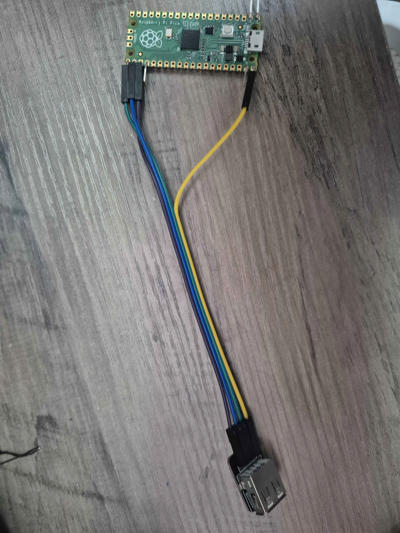
| Pico Pin | USB-A Pin | Signal |
|---|---|---|
| GPIO 16 (pin 21) | 3 | D+ (green) |
| GPIO 17 (pin 22) | 2 | D- (white) |
| VBUS (pin 40) | 1 | 5V (red) |
| GND (pin 38) | 4 | GND (black) |
Power note: VBUS on pin 40 passes through 5V from the Pico's own USB connection. If your controller needs more power (e.g. rumble), power the Pico via VSYS with a 5V supply and connect that supply to USB-A pin 1 instead.
Waveshare RP2040-Zero
| RP2040-Zero Pin | USB-A Pin | Signal |
|---|---|---|
| GPIO 10 | 3 | D+ (green) |
| GPIO 11 | 2 | D- (white) |
| 5V | 1 | 5V (red) |
| GND | 4 | GND (black) |
What You Need
- USB-A female breakout board (example) or a cut USB-A extension cable
- 4 jumper wires (or 22-26 AWG wire + soldering)
Tips
- Double-check D+ and D- — swapping them is the most common mistake and will silently fail
- Keep wires short — USB signal integrity degrades with long runs; under 15cm is ideal
- USB-A breakout boards are easier than cutting cables — labeled pins reduce wiring errors
- No hubs — connect your controller directly to the USB-A port (hubs are not reliable on PIO USB)
Troubleshooting
No controller detected: - Verify D+ and D- are not swapped - Check that VBUS is providing 5V to the USB-A connector - Try a different controller or cable - Confirm you flashed the correct firmware for your board
Controller disconnects or is flaky: - Shorten your wires - Check for cold solder joints - Some controllers draw more current than VBUS can supply — use external 5V power
Works with some controllers but not others: - Check the controller compatibility list for supported devices
Console Connector Pinouts
Console-specific wiring is documented with each adapter:
- PCEngine / TurboGrafx-16 — 8-pin DIN
- GameCube / Wii — Controller cable
- Dreamcast — Maple bus connector
- Nuon — Polyface serial
- 3DO — DB9 with level shifters
- Neo Geo — DB15