Dreamcast (usb2dc)
USB/BT controller to Dreamcast console adapter using the Maple Bus protocol.
Supported Boards
| Build Target |
Board |
Maple Pins |
Notes |
usb2dc_kb2040 |
Adafruit KB2040 |
GPIO 2 / GPIO 3 |
Default build |
usb2dc_rp2040zero |
Waveshare RP2040-Zero |
GPIO 14 / GPIO 15 |
USB4Maple-compatible pinout |
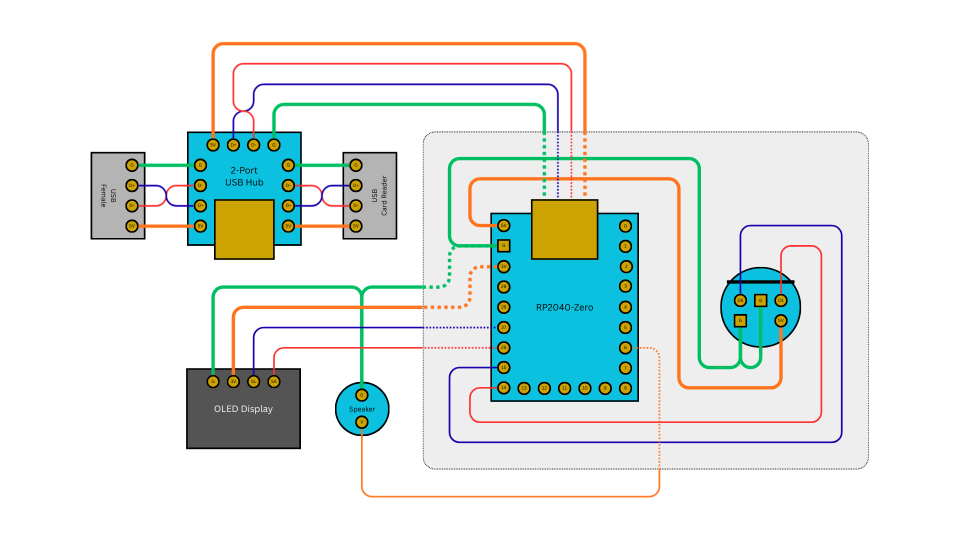
Wiring — RP2040-Zero (USB4Maple-compatible)
Uses the same pinout as USB4Maple, so existing USB4Maple hardware can run Joypad OS firmware as a drop-in replacement.
| Signal |
Dreamcast Pin |
RP2040-Zero GPIO |
| Data Line A (SDCKA) |
Pin 1 |
GP14 |
| Data Line B (SDCKB) |
Pin 5 |
GP15 |
| +5V |
Pin 3 |
5V |
| GND |
Pin 2, Pin 4 |
GND |
Wiring — KB2040
| Signal |
Dreamcast Pin |
KB2040 GPIO |
| Data Line A (SDCKA) |
Pin 1 |
GP2 |
| Data Line B (SDCKB) |
Pin 5 |
GP3 |
| +5V |
Pin 3 |
RAW/5V |
| GND |
Pin 2, Pin 4 |
GND |
Dreamcast Controller Connector Pinout
Looking at the controller plug (male, from controller cable):
     ___
   /  5  \
  | 4   3 |
  | 2   1 |
   \_____/
| Pin |
Signal |
Description |
| 1 |
SDCKA |
Data line A |
| 2 |
GND (Sense) |
Ground / device detect |
| 3 |
+5V |
Power |
| 4 |
GND |
Ground |
| 5 |
SDCKB |
Data line B |
| USB/BT Input |
Dreamcast Output |
| B1 |
A |
| B2 |
B |
| B3 |
X |
| B4 |
Y |
| L1 |
L Trigger (digital) |
| R1 |
R Trigger (digital) |
| L2 |
D button |
| R2 |
R Trigger (analog) |
| L3 |
Z |
| R3 |
C |
| S1 |
D (2nd Start) |
| S2 |
Start |
| D-pad |
D-pad |
| Guide |
Start |
Features
- Up to 4 players via Maple Bus
- Analog triggers (L/R)
- Rumble / Puru Puru Pack feedback
- Player LED color assignment (Orange P1, Blue P2, Red P3, Green P4)