USB Host Wiring Guide
How to wire a USB-A host port to your RP2040/RP2350 board for connecting controllers.
Note: The Adafruit Feather RP2040 USB Host has a built-in USB-A port — no wiring needed. This guide is for boards that require an external USB-A connector.
How It Works
Joypad uses PIO-based USB host (bit-banged via the RP2040's PIO1 peripheral). This allows simultaneous USB host and device — the native USB port acts as device (for flashing and USB output modes) while PIO USB provides the host port for controllers.
- Full Speed (12 Mbps) only
- D+ and D- must be on consecutive GPIOs (D- = D+ + 1)
- PIO1 is used for USB host (PIO0 is reserved for NeoPixel/status LED)
Pin Reference
| Board | D+ | D- | VBUS | Notes |
|---|---|---|---|---|
| Raspberry Pi Pico | GPIO 16 | GPIO 17 | VBUS (pin 40) | |
| Raspberry Pi Pico W | GPIO 16 | GPIO 17 | VBUS (pin 40) | |
| Raspberry Pi Pico 2 W | GPIO 16 | GPIO 17 | VBUS (pin 40) | |
| Adafruit Feather RP2040 USB Host | GPIO 16 | GPIO 17 | GPIO 18 | Built-in USB-A port, no wiring needed |
| Waveshare RP2040-Zero | GPIO 10 | GPIO 11 | 5V | Compact boards |
| Waveshare RP2350A USB-A | GPIO 12 | GPIO 13 | 5V | Has built-in USB-A port |
USB-A Connector Pinout
| USB-A Pin | Signal | Color (typical) |
|---|---|---|
| 1 | VBUS (+5V) | Red |
| 2 | D- | White |
| 3 | D+ | Green |
| 4 | GND | Black |
Wiring
Raspberry Pi Pico / Pico W / Pico 2 W
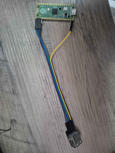
| Pico Pin | USB-A Pin | Signal |
|---|---|---|
| GPIO 16 (pin 21) | 3 | D+ (green) |
| GPIO 17 (pin 22) | 2 | D- (white) |
| VBUS (pin 40) | 1 | 5V (red) |
| GND (pin 38) | 4 | GND (black) |
Power note: VBUS on pin 40 passes through 5V from the Pico's own USB connection. If you need more power (multiple controllers, rumble), use an externally powered USB hub on the host port, or power the Pico via VSYS with a 5V supply and connect that supply to USB-A pin 1 instead.
Waveshare RP2040-Zero
| RP2040-Zero Pin | USB-A Pin | Signal |
|---|---|---|
| GPIO 10 | 3 | D+ (green) |
| GPIO 11 | 2 | D- (white) |
| 5V | 1 | 5V (red) |
| GND | 4 | GND (black) |
What You Need
- USB-A female breakout board (example) or a cut USB-A extension cable
- 4 jumper wires (or 22-26 AWG wire + soldering)
- USB hub (optional, for multiple controllers)
Tips
- Double-check D+ and D- — swapping them is the most common mistake and will silently fail
- Keep wires short — USB signal integrity degrades with long runs; under 15cm is ideal
- Use a USB hub for multiple controllers — connect the hub to your wired USB-A port
- Powered hubs recommended for 3+ controllers or when using rumble-heavy controllers (Xbox, DualShock)
- USB-A breakout boards are easier than cutting cables — labeled pins reduce wiring errors
Troubleshooting
No controller detected: - Verify D+ and D- are not swapped - Check that VBUS is providing 5V to the USB-A connector - Try a different controller or cable - Confirm you flashed the correct firmware for your board
Controller disconnects or is flaky: - Shorten your wires - Check for cold solder joints - Try a powered USB hub - Some controllers draw more current than VBUS can supply
Works with some controllers but not others: - High-power controllers (Xbox, DS4 with light bar) may need a powered hub - Check HARDWARE.md for the compatibility list